【STM32】CubeMX+HAL 点亮 LED
Author:AXYZdong
自动化专业 工科男
有一点思考,有一点想法,有一点理性!
定个小小目标,努力成为习惯!在最美的年华遇见更好的自己!
1. 配置STM32CubeMX
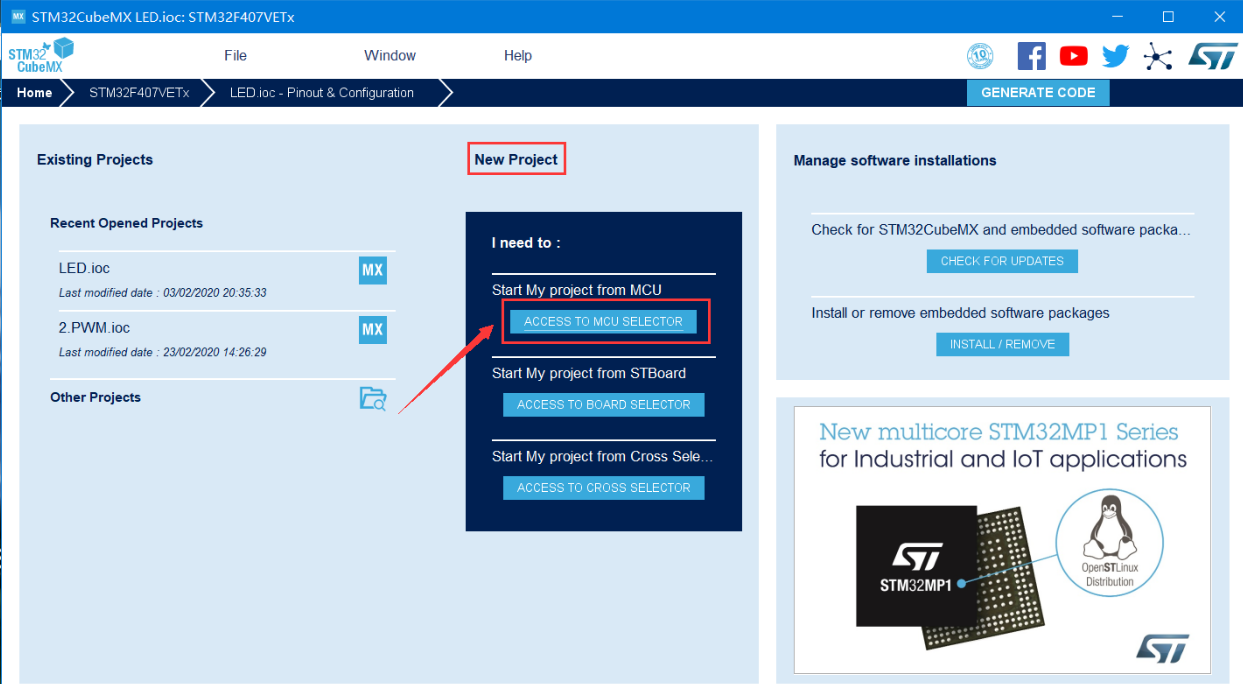
【1.1】打开软件:

【1.2】 在 STM32CubeMX 的主界面中,点击 功能框中的 功能按钮,从 MCU 开始新的工程。
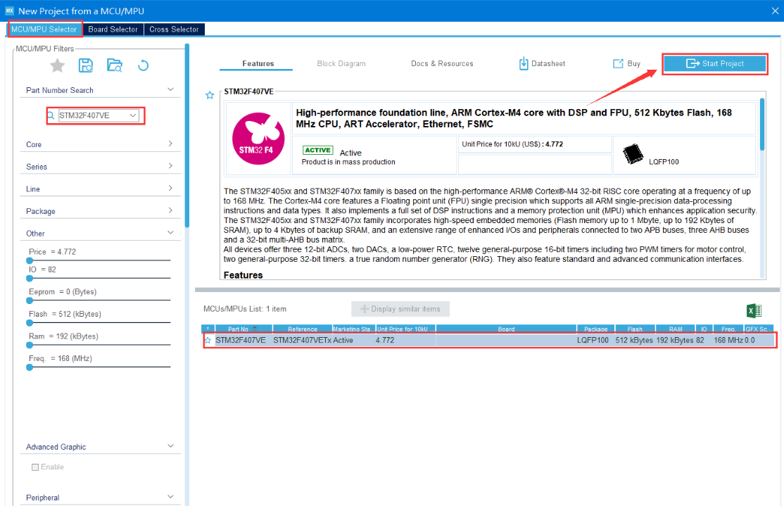
【1.3】 在弹出对话框的 选项卡中,首先,在左侧搜索框中输入该工 程需要使用的芯片型号 ,然后,用鼠标在右下方的芯片列表中选择具体的 芯片型号,接着点击右上角的 按钮,开始工程的各项配置。
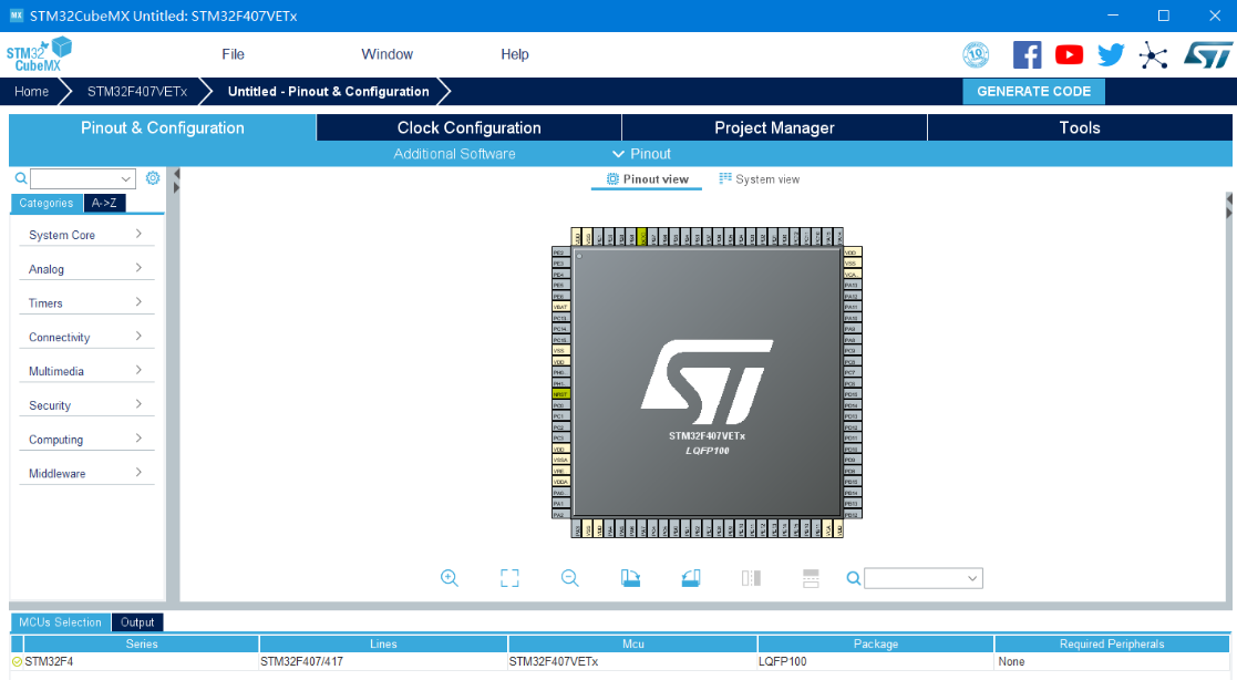
【1.4】 工程配置的主界面有四个菜单:、、 和 。
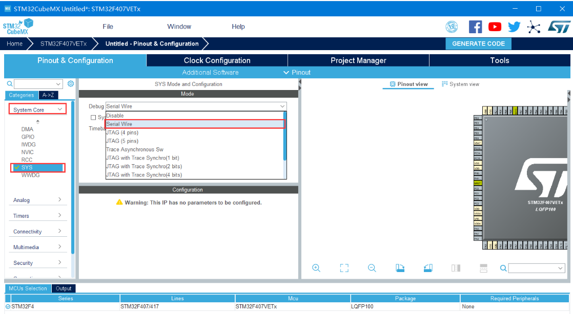
【1.5】 在 界面左侧的菜单中,选择 菜单项中的 ,在点击其右边展开的 功能框中配置工程的仿真调试方式。我使用的是 接口的仿真器,点击“Debug”下拉列表,选择 选项。
注:不同接口仿真器可以选择不同的调试方式。
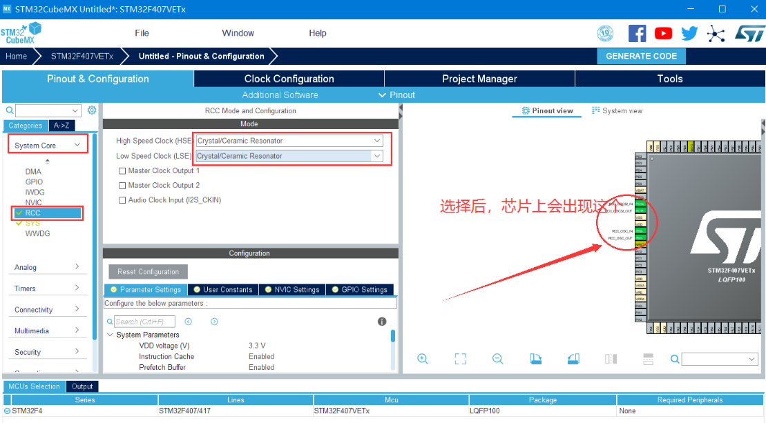
【1.6】在 界面左侧的菜单中,选择 菜单项中的 ,在点击其右边展开的 功能框中时钟源。如果你的芯片使用外部晶振,则 在 和 下拉列表中选择。
注:一般开发板上都会有两个外部晶振。
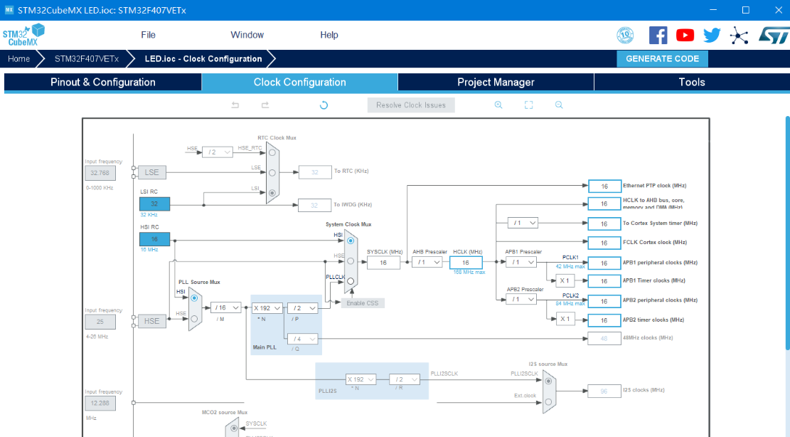
【1.7】点亮LED,这边时钟树默认就可以了,后面如果用到其他外设就有可能要设置时钟树了。
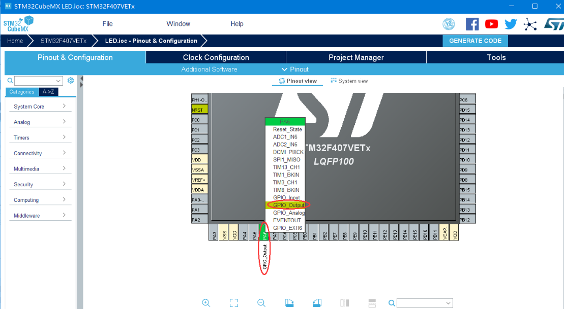
【1.8】LED 引脚接在 PA6 上,所以,需要将 PA6 引脚设置 为 GPIO 输出功能。
完成功能选择的引脚上会标志一个图钉并会根据不同功能填充不同的颜色,同时在该引脚旁边标识出所选定的功能。
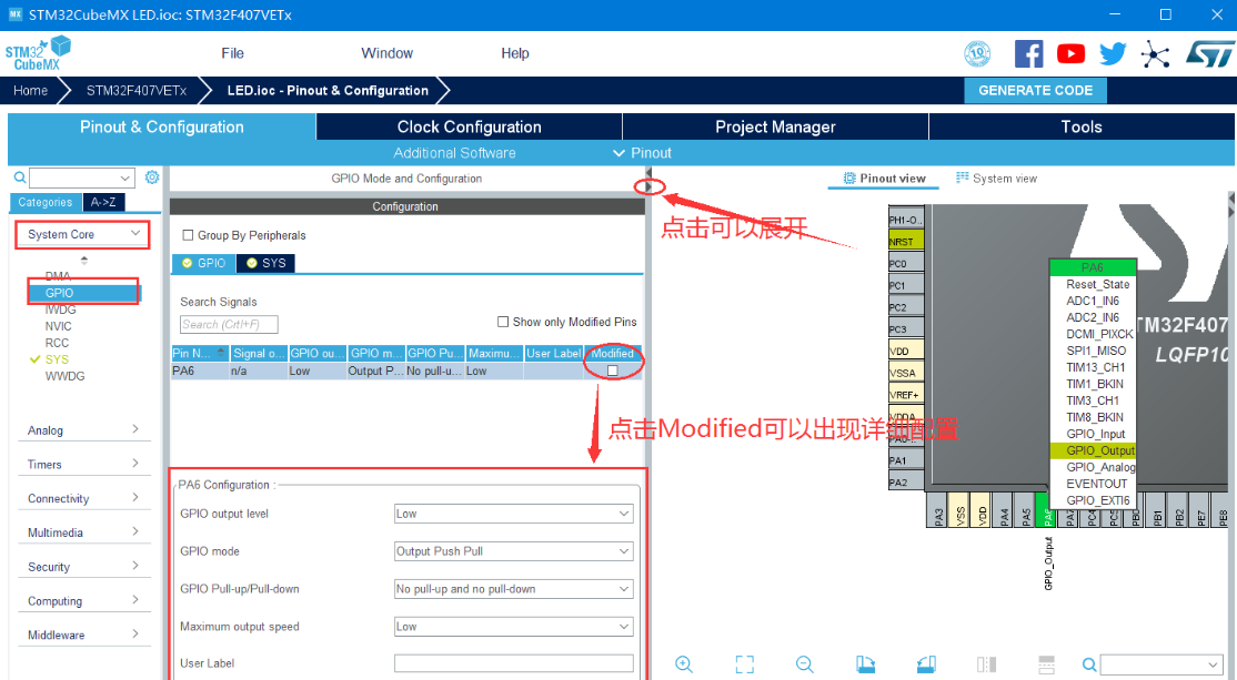
【1.9】 在 界面左侧的菜单中,选择 菜单项中的 ,点击小三角符号,向右边展开 GPIO 的功能框,在这里可以对所有选择的芯片引脚的输入和输出功能进行参数配置。
本次工程中 “SYS” 中设置了仿真调试引脚,在 “RCC” 中设置了外部晶振引脚, 在 “GPIO” 中设置了 LED 的控制引脚。选择不同的选项卡,就会看到其相关的芯片引脚, 可以根据具体需要对其属性参加修改配置。
【1.10】当把工程的引脚和外设全部配置完成后,点击主界面中的 菜单项,进入工程相关的参数配置界面。
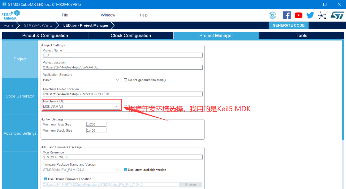
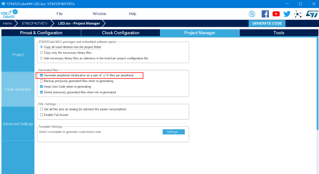
【1.11】在工程参数配置界面左侧的 菜单项中,将 中的第一项打钩。
这样生成的工程将会为你配置的每一个外设生成对应的.c 文件和.h 文件。
【1.12】点击主界面右上角的 , 开始生成工程代码。
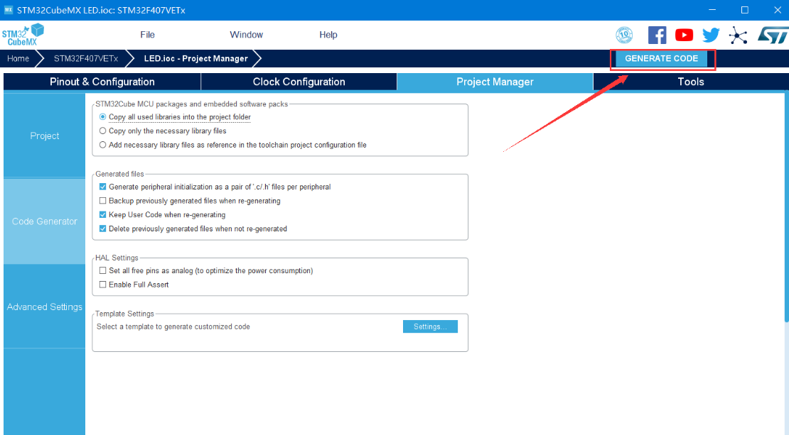
【1.13】代码生成后会弹出一个提示框,点击 按钮可直接打开生成工程代 码所在的文件夹
也可以点击 按钮直接完成,但不会关闭 STM32CubeMX。
2. 添加代码
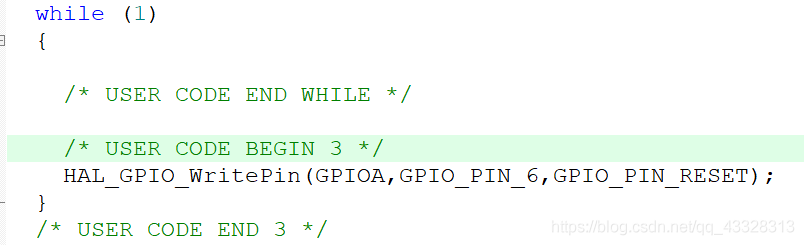
只需添加一行代码即可:
HAL_GPIO_WritePin(GPIOA,GPIO_PIN_6,GPIO_PIN_RESET);下面贴出主要的生成代码:
2.1 gpio.c
/**
  ******************************************************************************
  * File Name          : gpio.c
  * Description        : This file provides code for the configuration
  *                      of all used GPIO pins.
  ******************************************************************************
  * @attention
  *
  * © Copyright (c) 2020 STMicroelectronics.
  * All rights reserved.
  *
  * This software component is licensed by ST under BSD 3-Clause license,
  * the "License"; You may not use this file except in compliance with the
  * License. You may obtain a copy of the License at:
  *                        opensource.org/licenses/BSD-3-Clause
  *
  ******************************************************************************
  */

/* Includes ------------------------------------------------------------------*/
#include "gpio.h"
/* USER CODE BEGIN 0 */

/* USER CODE END 0 */

/*----------------------------------------------------------------------------*/
/* Configure GPIO                                                             */
/*----------------------------------------------------------------------------*/
/* USER CODE BEGIN 1 */

/* USER CODE END 1 */

/** Configure pins as
        * Analog
        * Input
        * Output
        * EVENT_OUT
        * EXTI
*/
void MX_GPIO_Init(void)
{

  GPIO_InitTypeDef GPIO_InitStruct = {0};

  /* GPIO Ports Clock Enable */
  __HAL_RCC_GPIOA_CLK_ENABLE();

  /*Configure GPIO pin Output Level */
  HAL_GPIO_WritePin(GPIOA, GPIO_PIN_6, GPIO_PIN_RESET);

  /*Configure GPIO pin : PA6 */
  GPIO_InitStruct.Pin = GPIO_PIN_6;
  GPIO_InitStruct.Mode = GPIO_MODE_OUTPUT_PP;
  GPIO_InitStruct.Pull = GPIO_NOPULL;
  GPIO_InitStruct.Speed = GPIO_SPEED_FREQ_LOW;
  HAL_GPIO_Init(GPIOA, &GPIO_InitStruct);

}

/* USER CODE BEGIN 2 */

/* USER CODE END 2 */

/************************ (C) COPYRIGHT STMicroelectronics *****END OF FILE****/
2.2 main.c
/* USER CODE BEGIN Header */
/**
  ******************************************************************************
  * @file           : main.c
  * @brief          : Main program body
  ******************************************************************************
  * @attention
  *
  * © Copyright (c) 2020 STMicroelectronics.
  * All rights reserved.
  *
  * This software component is licensed by ST under BSD 3-Clause license,
  * the "License"; You may not use this file except in compliance with the
  * License. You may obtain a copy of the License at:
  *                        opensource.org/licenses/BSD-3-Clause
  *
  ******************************************************************************
  */
/* USER CODE END Header */

/* Includes ------------------------------------------------------------------*/
#include "main.h"
#include "gpio.h"

/* Private includes ----------------------------------------------------------*/
/* USER CODE BEGIN Includes */

/* USER CODE END Includes */

/* Private typedef -----------------------------------------------------------*/
/* USER CODE BEGIN PTD */

/* USER CODE END PTD */

/* Private define ------------------------------------------------------------*/
/* USER CODE BEGIN PD */

/* USER CODE END PD */

/* Private macro -------------------------------------------------------------*/
/* USER CODE BEGIN PM */

/* USER CODE END PM */

/* Private variables ---------------------------------------------------------*/

/* USER CODE BEGIN PV */

/* USER CODE END PV */

/* Private function prototypes -----------------------------------------------*/
void SystemClock_Config(void);
/* USER CODE BEGIN PFP */

/* USER CODE END PFP */

/* Private user code ---------------------------------------------------------*/
/* USER CODE BEGIN 0 */

/* USER CODE END 0 */

/**
  * @brief  The application entry point.
  * @retval int
  */
int main(void)
{
  /* USER CODE BEGIN 1 */

  /* USER CODE END 1 */


  /* MCU Configuration--------------------------------------------------------*/

  /* Reset of all peripherals, Initializes the Flash interface and the Systick. */
  HAL_Init();

  /* USER CODE BEGIN Init */

  /* USER CODE END Init */

  /* Configure the system clock */
  SystemClock_Config();

  /* USER CODE BEGIN SysInit */

  /* USER CODE END SysInit */

  /* Initialize all configured peripherals */
  MX_GPIO_Init();
  /* USER CODE BEGIN 2 */

  /* USER CODE END 2 */

  /* Infinite loop */
  /* USER CODE BEGIN WHILE */
  while (1)
  {

    /* USER CODE END WHILE */

    /* USER CODE BEGIN 3 */
		HAL_GPIO_WritePin(GPIOA,GPIO_PIN_6,GPIO_PIN_RESET);
  }
  /* USER CODE END 3 */
}

/**
  * @brief System Clock Configuration
  * @retval None
  */
void SystemClock_Config(void)
{
  RCC_OscInitTypeDef RCC_OscInitStruct = {0};
  RCC_ClkInitTypeDef RCC_ClkInitStruct = {0};

  /** Configure the main internal regulator output voltage
  */
  __HAL_RCC_PWR_CLK_ENABLE();
  __HAL_PWR_VOLTAGESCALING_CONFIG(PWR_REGULATOR_VOLTAGE_SCALE1);
  /** Initializes the CPU, AHB and APB busses clocks
  */
  RCC_OscInitStruct.OscillatorType = RCC_OSCILLATORTYPE_HSI;
  RCC_OscInitStruct.HSIState = RCC_HSI_ON;
  RCC_OscInitStruct.HSICalibrationValue = RCC_HSICALIBRATION_DEFAULT;
  RCC_OscInitStruct.PLL.PLLState = RCC_PLL_NONE;
  if (HAL_RCC_OscConfig(&RCC_OscInitStruct) != HAL_OK)
  {
    Error_Handler();
  }
  /** Initializes the CPU, AHB and APB busses clocks
  */
  RCC_ClkInitStruct.ClockType = RCC_CLOCKTYPE_HCLK|RCC_CLOCKTYPE_SYSCLK
                              |RCC_CLOCKTYPE_PCLK1|RCC_CLOCKTYPE_PCLK2;
  RCC_ClkInitStruct.SYSCLKSource = RCC_SYSCLKSOURCE_HSI;
  RCC_ClkInitStruct.AHBCLKDivider = RCC_SYSCLK_DIV1;
  RCC_ClkInitStruct.APB1CLKDivider = RCC_HCLK_DIV1;
  RCC_ClkInitStruct.APB2CLKDivider = RCC_HCLK_DIV1;

  if (HAL_RCC_ClockConfig(&RCC_ClkInitStruct, FLASH_LATENCY_0) != HAL_OK)
  {
    Error_Handler();
  }
}

/* USER CODE BEGIN 4 */

/* USER CODE END 4 */

/**
  * @brief  This function is executed in case of error occurrence.
  * @retval None
  */
void Error_Handler(void)
{
  /* USER CODE BEGIN Error_Handler_Debug */
  /* User can add his own implementation to report the HAL error return state */

  /* USER CODE END Error_Handler_Debug */
}

#ifdef  USE_FULL_ASSERT
/**
  * @brief  Reports the name of the source file and the source line number
  *         where the assert_param error has occurred.
  * @param  file: pointer to the source file name
  * @param  line: assert_param error line source number
  * @retval None
  */
void assert_failed(uint8_t *file, uint32_t line)
{
  /* USER CODE BEGIN 6 */
  /* User can add his own implementation to report the file name and line number,
     tex: printf("Wrong parameters value: file %s on line %d\r\n", file, line) */
  /* USER CODE END 6 */
}
#endif /* USE_FULL_ASSERT */

/************************ (C) COPYRIGHT STMicroelectronics *****END OF FILE****/
3. 总结
CubeMX+HAL 不需要理解底层寄存器的定义,使用起来非常方便
要理解生成的代码之间的逻辑联系,熟悉常用的 hal 函数
建议学完标准库后上手 CubeMX
猜你喜欢:
本次的分享就到这里

好书不厌百回读,熟读自知其中意。将学习成为习惯,用知识改变命运,用博客见证成长,用行动证明努力。
如果我的博客对你有帮助、如果你喜欢我的博客内容,请 “点赞” “评论” “收藏” 一键三连哦!
听说 👉 点赞 👈 的人运气不会太差,每一天都会元气满满呦!^ _ ^
码字不易,大家的支持就是我坚持下去的动力。点赞后不要忘了👉 关注 👈我哦!
如果以上内容有任何错误或者不准确的地方,欢迎在下面👇留个言。或者你有更好的想法,欢迎一起交流学习~~~